Bluetooth Pac-Man Connect & Play (MOD)
⚠ Just to clarify: This is not a Bluetooth mod for the console itself. It won’t let you connect a Bluetooth Controller to the Plug & Play device. Instead, this mod turns the entire console into a Bluetooth controller. You will lose access to the Pac-Man games, but you'll gain a functional joystick with two buttons controller.
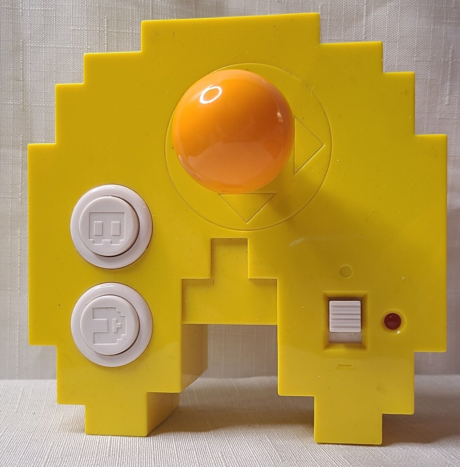
This is a step-by-step tutorial on how to convert your Pac-Man Connect & Play into a (very small) arcade/retro controller with ESP32!.
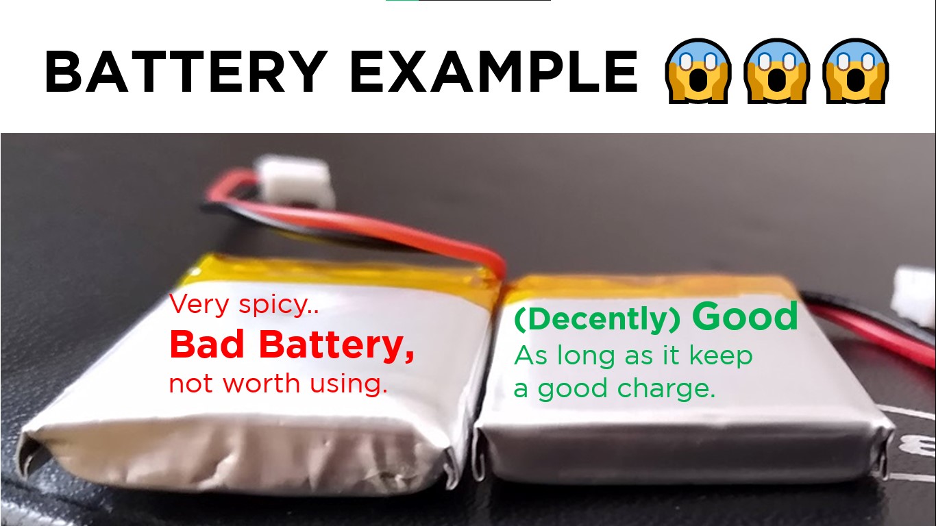
First, the necessary materials. Since this is a wireless mod, you will need a battery (either lithium or those old Cell phones batteries, whichever you prefer).
⬆ About the line above me, Please consider looking at your batterys before using them, ensure it's in good condition and avoid swollen or damaged batteries. Heres an example.
- ESP32
- A power switch (you can use the original one, though it may be tricky—but possible, and you keep the LED!)
- TP4056 (Supports Micro USB, Mini USB, and USB-C. In this case, we'll use USB-C.)
- A rechargable Battery. (ensure that is it good as described.)
- Wires (Ensure they are long enough for flexibility).
If you have all the materials ready, let's begin.
WARNING: This mod is reversible, but in some cases, it may not be.
Proceed at your own risk.
Step 1: Opening Your Pac-Man
All images are from the iFixit guide, as I already opened my console and lost the screws plus some really bad changes, ups.
Credits for the original autor of the awesome guide.
First, open the battery cover.
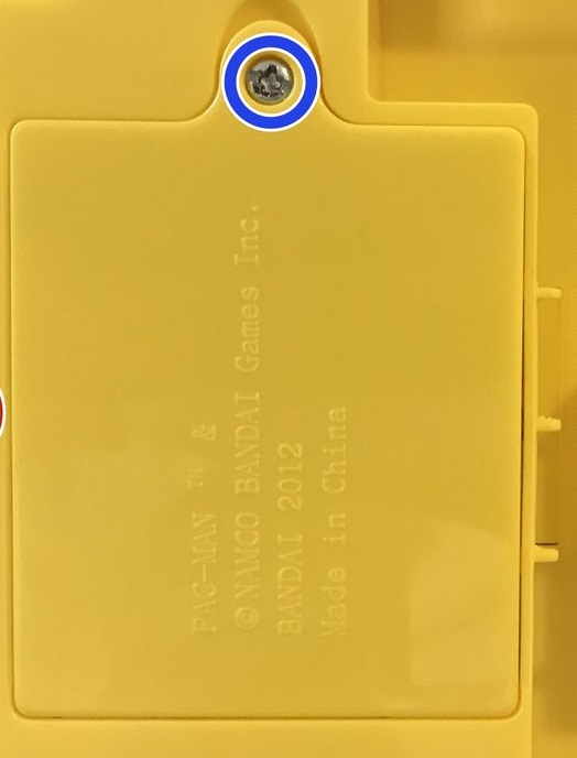
Now, remove all the red screws shown in the image.
Sorry if the image looks weird; it's the only back image I found and had to modify it.
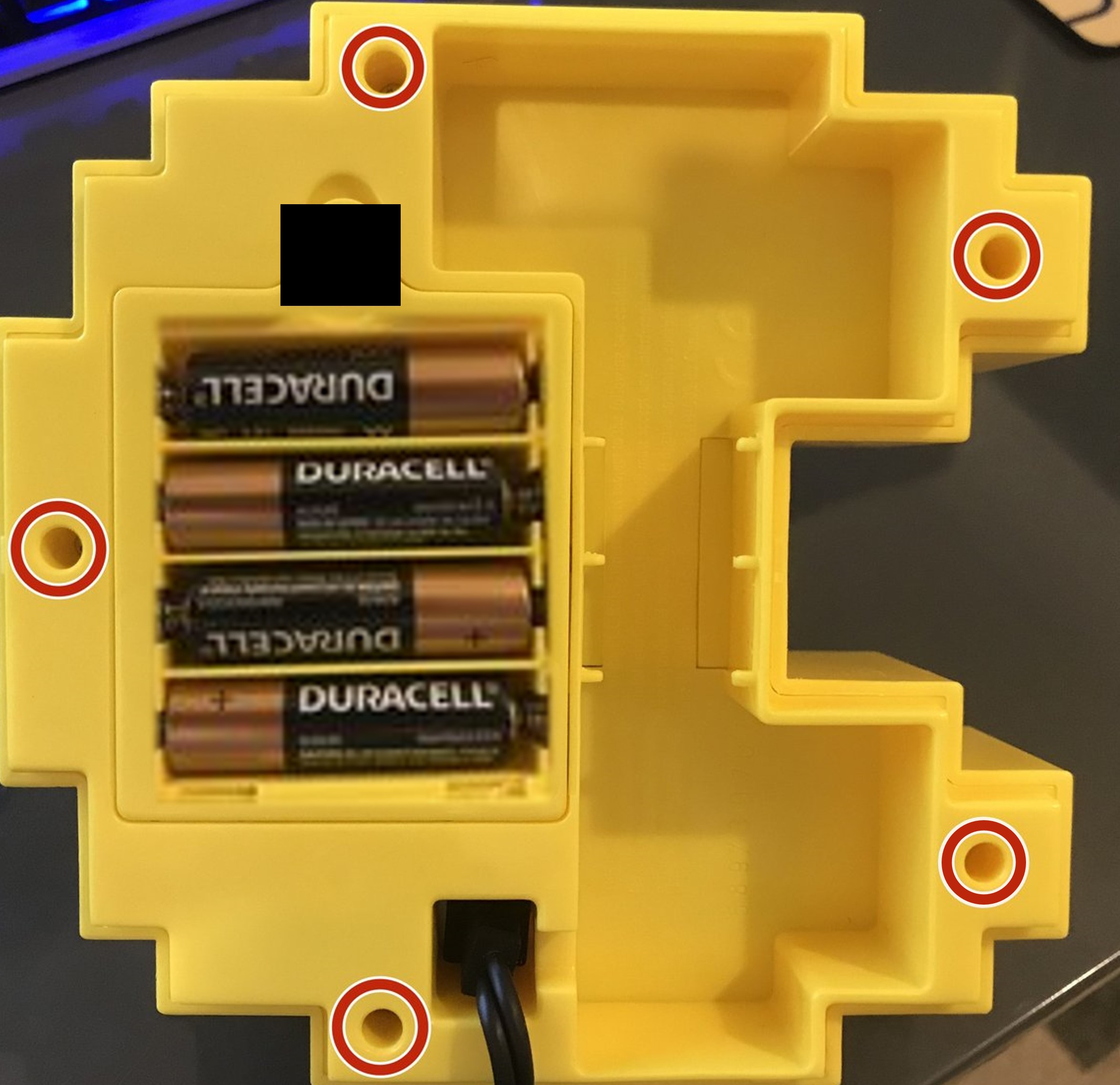
Don't forget to remove the batteries!
Open it gently, and now you are inside the Pac-Man unit!
DO NOT pull anything out immediately—many cables are soldered together and can break easily,
even tho they will be removed anyways, it is better to do it gently instead.
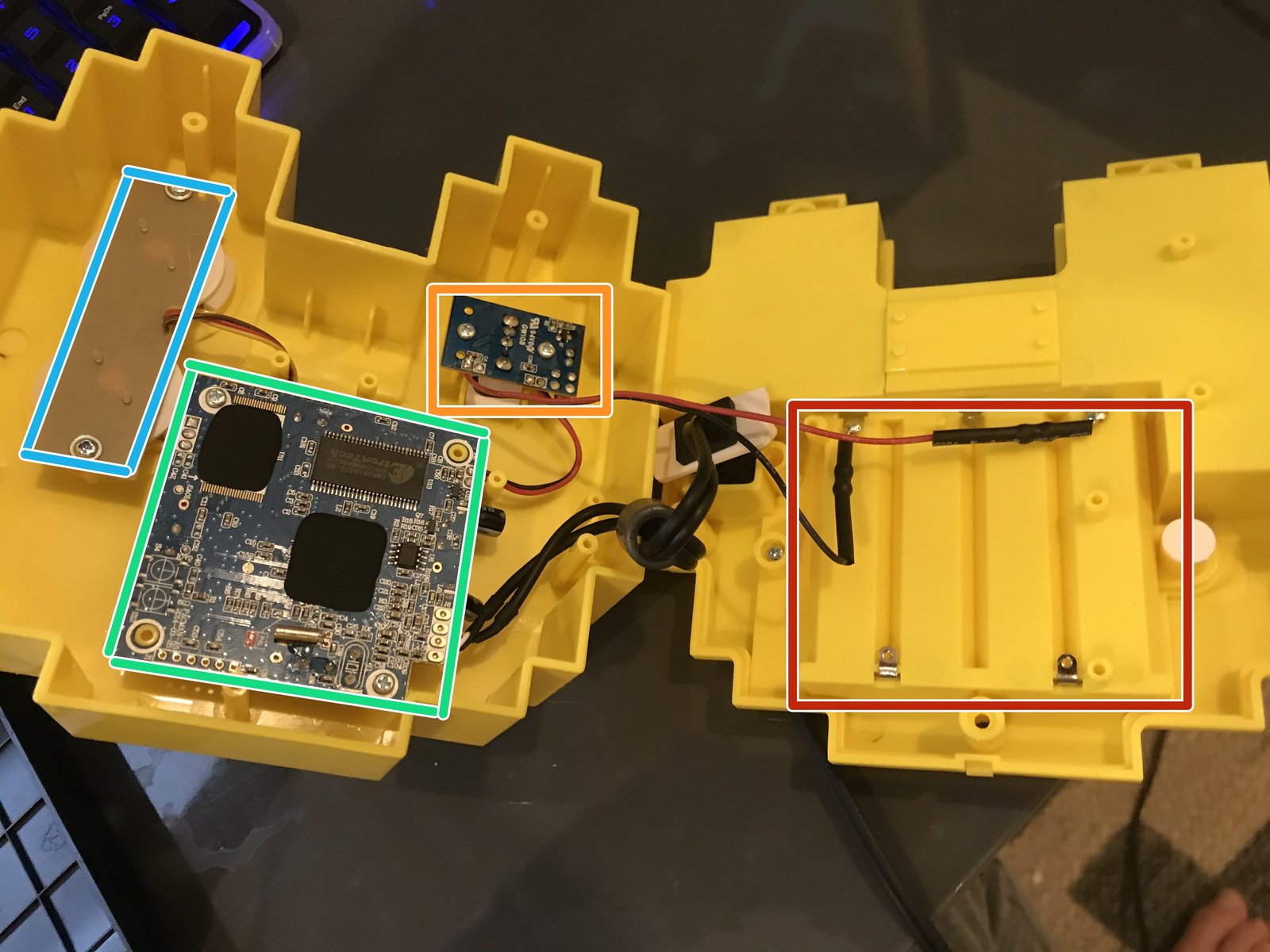
Hints for the colored boxes:
- Red: Battery compartment
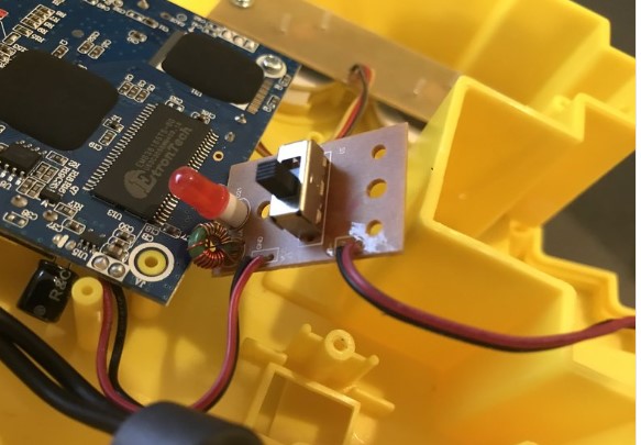
- Orange: Power switch and LED
- Green: Motherboard
- Blue: A and B button board
Step 2: Soldering
This part may seem difficult, and it kind of is, but it is necessary.
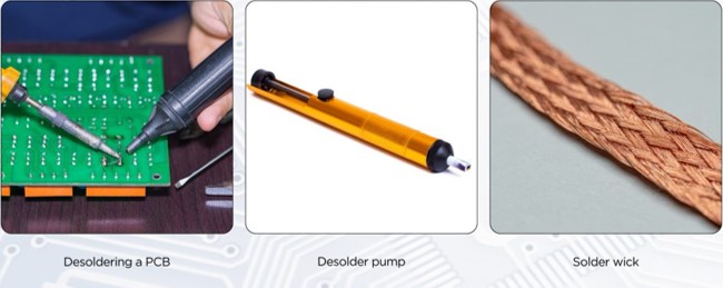
Here are the materials you can use for Desoldering, althought for this proyect you can just pull out the cables, but it IS not recommended.
First, remove the AV cables. Desoldering can be tricky, well only for me... But if necessary, gently pull out the cables. Some pads may break, but since we’re not using the motherboard, it's fine.
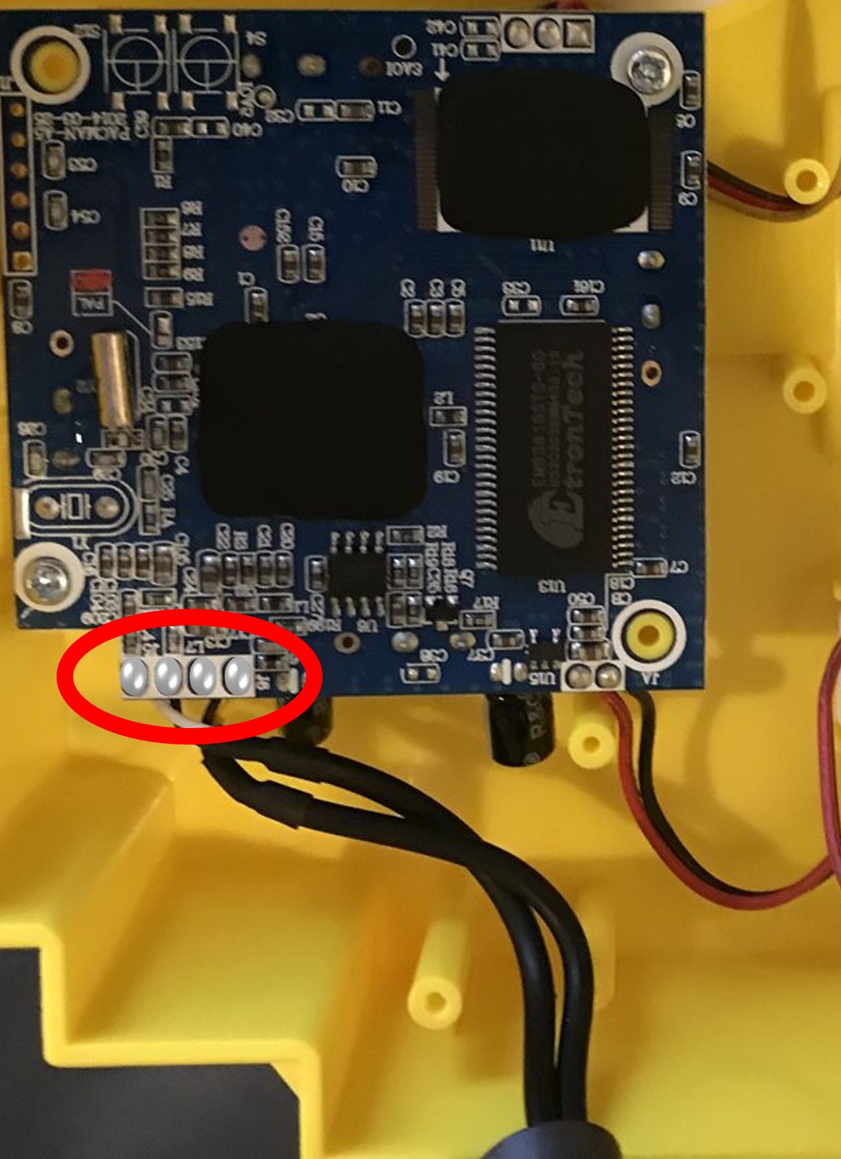
Next, remove the power switch cables from the motherboard.
If you plan to use the original switch, keep its cables but detach them on the motherboard.
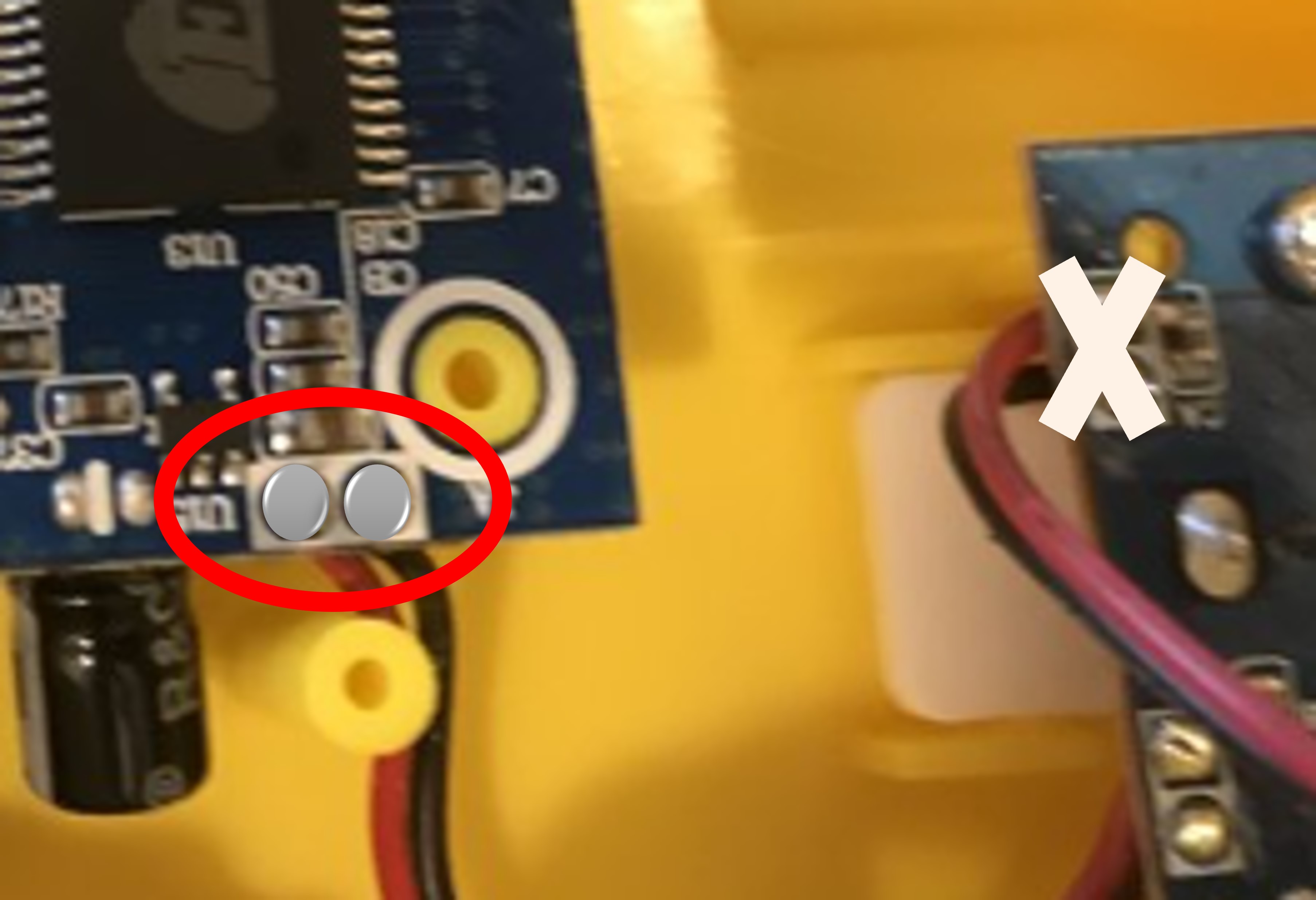
Remove all cables from the motherboard, the A & B button board, and the battery contacts.
Be gentle—never force anything.
Violence is never the answer... unless it doesn't cooperate at first try.
This is all the information I have for now. I will update this guide with more details soon.